Week 11 Stage: Speaker & Cabinet
Speaker, Cabinet and Air
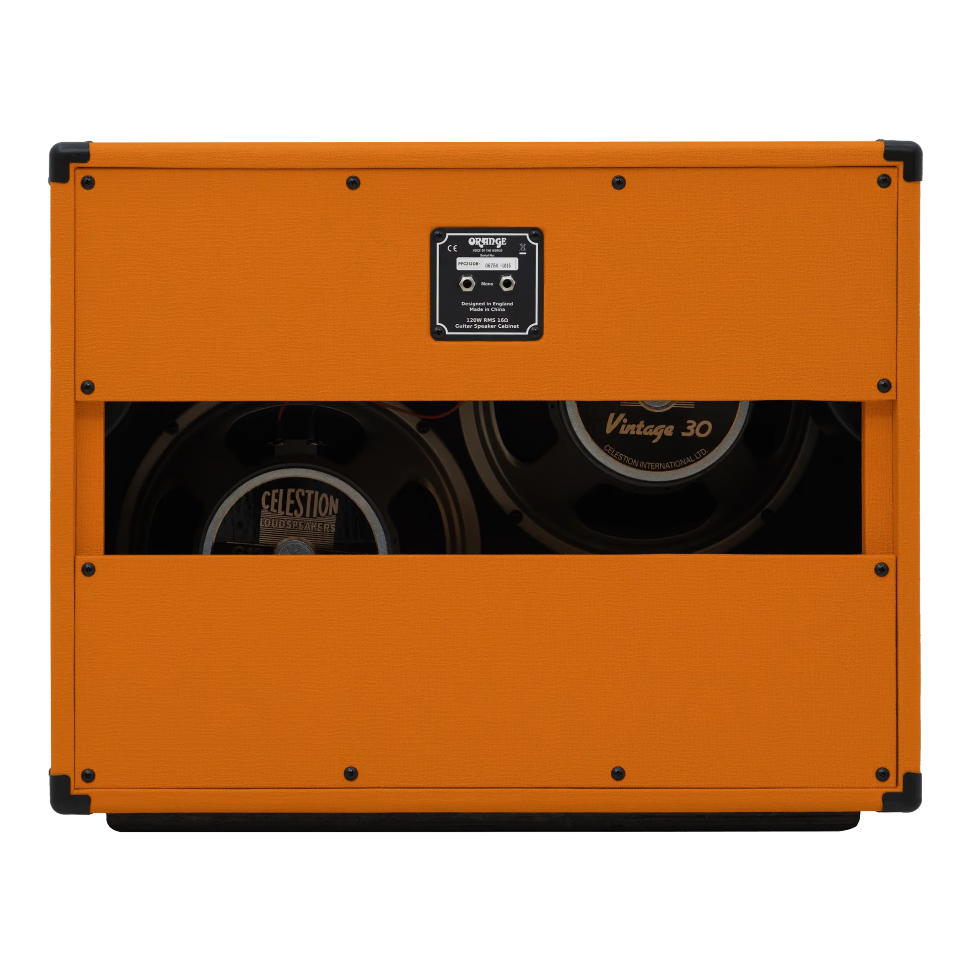
Photo: Ian Abbott · CC BY-SA 2.0
Why can the same amplifier sound dramatically different through different speakers and cabinets?
- InputAn electrical voltage at the amplifier's power output
- ProcessMechanical motion at the voice coil and cone, reshaped by the cabinet and radiated into the air
- OutputAcoustic sound — and, when recorded, whatever a microphone's position captures
Where we left off
The last physical stage before sound reaches the air
Week 10 followed the signal to the amplifier’s electrical output. That output still isn’t sound — it’s a voltage across a speaker terminal. Turning that voltage into acoustic pressure in the air is its own physical process, with its own way of reshaping the signal, and it’s the last stage in the chain before a listener, or a microphone, hears anything at all. By the end of this week you should be able to explain how a loudspeaker converts an electrical signal into mechanical motion; explain why guitar speakers are deliberately not flat, transparent transducers; describe resonance conceptually as part of why a speaker’s response isn’t flat; compare open-back and closed-back cabinets conceptually; explain, briefly, that radiated sound depends on frequency and direction; explain that microphone type, position, angle, and distance all affect a recorded tone; and connect a cabinet’s impulse response back to Week 9’s delay/reverb ideas.
- Voice coil + magnet: force
- Cone: mechanical motion
- Cabinet: shapes radiation
- Mic position: shapes what's captured
Transduction
Electrical signal to mechanical motion
A loudspeaker’s voice coil sits inside a fixed magnetic field. Current from the amplifier flows through the coil, and a current-carrying conductor in a magnetic field experiences a force — so the coil, attached to the cone, moves. Reverse the current’s direction and the force reverses too. The amplifier’s electrical signal is therefore converted directly into the cone’s back-and-forth mechanical motion, and that motion is what pushes on the surrounding air.
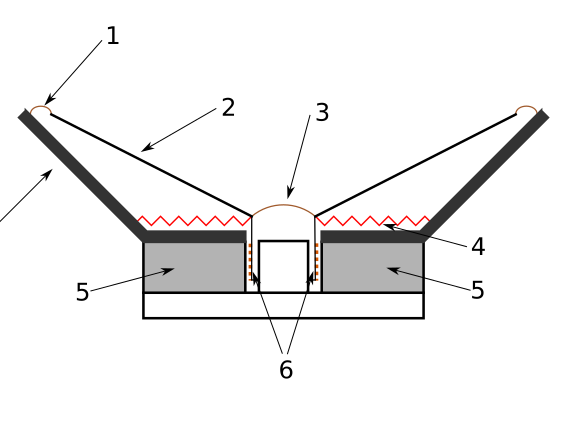
- Surround — the flexible rim that lets the cone move
- Cone — the surface that pushes the surrounding air
- Dust cap — covers the coil/pole gap at the centre
- Spider — a rear suspension that keeps the coil centred
- Magnet — supplies the fixed magnetic field
- Voice coil — carries the amplifier's current, sitting in the magnet's gap
- Basket — the rigid frame everything else is mounted to
Diagram: Maksim (original), Harkonnen2 (SVG) · CC BY-SA 3.0 / GFDL, via Wikimedia Commons
Coloration, not accident
Why guitar speakers aren't flat
A studio monitor is designed to reproduce a signal as transparently as possible across the audible range. A guitar speaker is not designed that way, and isn’t trying to be: its cone, surround, and magnet structure have their own mechanical resonances, and its frequency response rolls off and peaks in ways a “flat” transducer deliberately avoids. That coloration isn’t a flaw to be corrected — for a guitar amplifier, it’s a major, expected part of the final tone.
- Flat (unfiltered)
- Bright small speaker
- Darker cabinet
- Resonant cabinet
A bright small speaker rolls off early at the low end but extends further at the top; a darker cabinet rolls off the highs much sooner; a resonant cabinet peaks near both ends instead of rolling off smoothly. None of these is “correct” — they’re different, deliberate colorations, the same way different clipping topologies in Week 6 were different, deliberate distortions rather than one being more accurate than another. A speaker cone, its surround, and the air trapped inside a cabinet all have natural mechanical or acoustic resonances — the same general idea Week 7 introduced for electrical filters, just realised here mechanically and acoustically instead of electrically. This course treats resonance here only conceptually, not as detailed mechanical or room acoustics.
The enclosure
Cabinet design, radiation, and the microphone
The box a speaker is mounted in matters too. An open-back cabinet leaves the rear of the cone exposed, so sound radiates from both the front and the back; a closed-back cabinet seals the rear, so only the front radiates. The cabinet’s internal volume, and how many speakers share it, also shape the result. This course doesn’t require advanced enclosure-design theory — only that the enclosure is a deliberate design choice, not incidental packaging.
How sound radiates from a cone also depends on frequency: lower frequencies tend to radiate in most directions fairly evenly, while higher frequencies become more directional, radiating more narrowly along the speaker’s axis. That’s one reason a guitar cabinet can sound different depending on where, relative to the speaker, a listener or a microphone stands. When a cabinet is recorded rather than heard directly in the room, the microphone becomes part of the signal path too: different microphone types respond differently, and where a microphone is placed relative to the cone (on-axis versus off-axis, near the center versus near the edge), the angle it’s aimed at, and the distance from the cabinet, all affect what’s actually captured. This course introduces that these factors matter conceptually — it does not turn into a recording-engineering course, and doesn’t claim any one placement is universally “correct.”
Week 9 introduced the impulse response as a way to describe a linear system’s behaviour: excite it with a single impulse, and its output over time tells you everything about how it will treat any input. A recorded speaker-cabinet-microphone combination has its own impulse response too — it captures, in one linear description, the combined effect of the speaker, the cabinet, the microphone, and its position, all at once. That’s exactly why a “cabinet impulse response” is a genuinely useful, reusable recording: convolving a signal with it (Week 9’s convolution reverb, again) applies that whole combined coloration in one step.
Try it
A simplified virtual cabinet
- Physical mechanism
- Signal transformation
- Waveform / spectral consequence
- Audible consequence
Switch between cabinet response profiles and watch the frequency-response curve change shape — a bright, small-speaker-like curve, a darker cabinet that rolls off sooner, a resonant cabinet with peaks near both ends. Then move the microphone from center to edge, and further away, and watch a second, gentler rolloff stack on top of whichever cabinet profile is selected. This is a conceptual model, explicitly not a physically accurate speaker, cabinet, or microphone simulation.
Audio never plays automatically — press play to hear it, press again to stop.
Bright small speaker, mic on-axis (center), 15 cm away.
A conceptual model, not a physical simulation: the cabinet profile is a resonant high-pass cascaded with a resonant low-pass, and microphone position/distance apply one further low-pass on top. Real speakers, cabinets, and microphones each have far more particular behaviour than this — the point here is only that all three reshape frequency content before a signal is heard.
Takeaways
What this week establishes
A loudspeaker's voice coil sits in a magnet's field; current through it creates a force, converting the amplifier's electrical signal directly into the cone's mechanical motion.
Guitar speakers are deliberately not flat, transparent transducers — their frequency-response coloration is a major, expected part of guitar tone, not a flaw.
Resonance in a cone, surround, or cabinet volume shows up as a peak in frequency response, the mechanical/acoustic counterpart to a high-Q electrical filter.
Open-back cabinets radiate from both the front and back of the cone; closed-back cabinets radiate only from the front; internal volume and speaker count also matter — none of this requires advanced enclosure engineering to understand conceptually.
Radiated sound depends on frequency and direction, and microphone type, position, angle, and distance all further shape what a recording captures.
A cabinet impulse response captures the combined linear behaviour of speaker, cabinet, microphone, and position in one reusable recording — directly connecting back to Week 9's impulse-response and convolution ideas.
The chain
Where this sits, and what comes next
- 01INPUTWhat Is Guitar Tone?
- 02STRINGThe Vibrating String
- 03PICKUPFrom Vibration to Voltage
- 04CIRCUITThe Guitar Is a Circuit
- 05DRIVEGain, Headroom and Clipping
- 06DISTORTIONInside overdrive, distortion and fuzz
- 07FILTERFilters, EQ and Tone Stacks
- 08MODULATIONModulation: Phase, Pitch and Motion
- 09SPACEDelay, Reverb and Space
- 10AMPInside the Guitar Amplifier
- 11SPEAKERSpeaker, Cabinet and Air
- 12OUTPUTEngineering the Complete Tone
Week 10 ended at the electrical power output of the amplifier. This week converted that signal into acoustic sound: a loudspeaker’s mechanical motion, shaped further by the cabinet it sits in and, when recorded, by a microphone’s position. The complete physical signal path — string, pickup, circuit, effects, amplifier, speaker, cabinet, air — is now established. Week 12 returns to the original question this course opened with, and asks how to reason backwards from a desired sound to a deliberately engineered signal chain across all of it.
- Physical mechanism
- Signal transformation
- Waveform / spectral consequence
- Audible consequence