Week 04 Stage: Circuit
The Guitar Is a Circuit
Photo: Maxim J · CC BY-SA 2.0
Why can passive components inside a guitar significantly change its tone?
- InputA voltage from the pickup
- ProcessResistors, potentiometers, and a capacitor
- OutputA filtered signal, before any pedal
Where we left off
From a voltage to a filtered signal
Week 3 followed the string’s motion into a voltage at the pickup. That voltage doesn’t reach the amplifier untouched — inside the guitar, and along the cable to the amp, it passes through resistors, potentiometers, and capacitors that are entirely passive (no power supply, no amplification) yet still measurably reshape the signal’s frequency content before anything resembling a pedal is involved. By the end of this week you should be able to identify resistors, potentiometers, and capacitors in a simplified guitar circuit; describe what volume and tone controls actually do; explain, qualitatively, how resistance and capacitance combine into a filter; relate cable capacitance to high-frequency response; and read a simple frequency-response curve.
- Resistance & capacitance
- RC low-pass filtering
- Frequency response
- Filtered tone
Inside the guitar
A simplified passive circuit
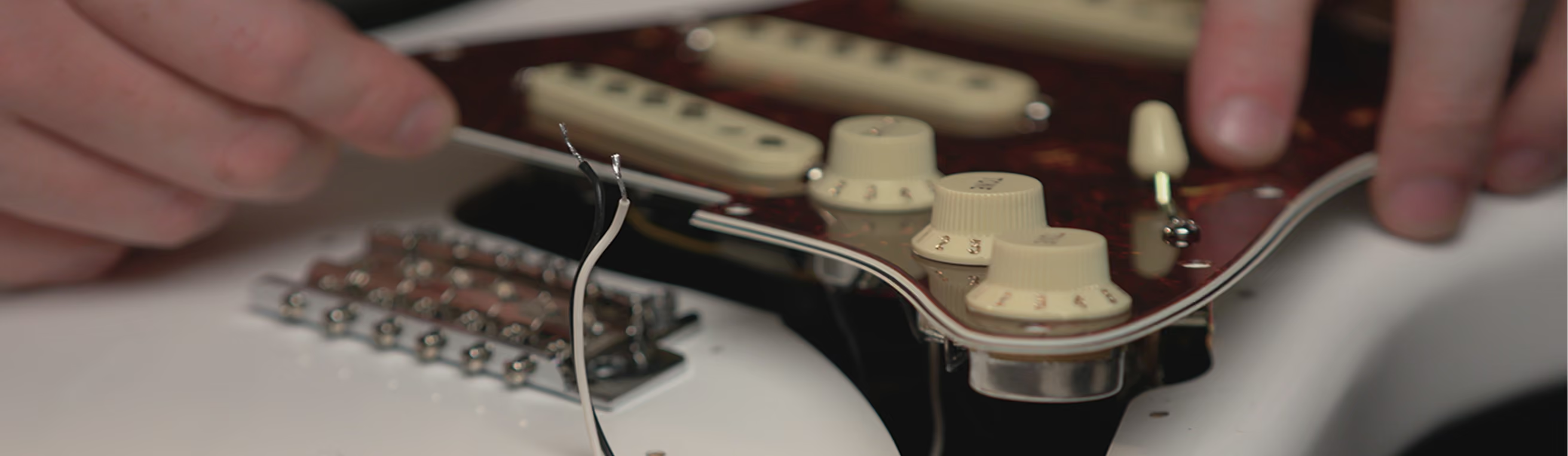
The pickup behaves like a voltage source feeding a chain of passive parts. A potentiometer is a variable resistor: as a volume control, it’s wired to send a variable fraction of the signal to ground instead of onward — turning the pot down sends proportionally more away. The tone control uses a potentiometer differently — as a variable resistance in series with a fixed capacitor to ground. A capacitor’s impedance falls as frequency rises, so more of the signal’s high-frequency content gets diverted to ground as that resistance changes.
The filter
The tone control as an RC low-pass
Together, the tone pot’s resistance and the fixed capacitor form a low-pass filter, with cutoff frequency f_c = 1/(2πRC): a larger resistance or a larger capacitance both lower the cutoff, removing more of the high end. This is exactly why a passive tone control isn’t simply a volume control for treble — it selectively removes high-frequency energy above the cutoff rather than turning everything down equally.
Cable and buffers
Pickup and cable interaction
A pickup isn’t an ideal voltage source — its own construction gives it a non-negligible source impedance, and the instrument cable connecting it to the amplifier adds its own capacitance in the process. That cable capacitance, combined with the guitar’s and amp’s input impedance, forms another low-pass effect: a longer or higher-capacitance cable can measurably soften the signal’s high end before the amplifier ever sees it. A buffer — briefly, an active stage placed early in the signal path — reduces this interaction between a high-impedance source and whatever comes after it, without needing this week’s circuit analysis to go any deeper.
Try it
The tone-control simulator
- Physical mechanism
- Signal transformation
- Waveform / spectral consequence
- Audible consequence
Adjust the pot’s resistance, the tone capacitor, and the cable capacitance below and watch the combined frequency-response curve and its cutoff frequency update — computed directly from f_c = 1/(2πRC), with cable capacitance folded in as extra capacitance alongside the tone capacitor.
Cutoff: Hz
Audio never plays automatically — press play to hear it, press again to stop.
One combined RC low-pass stands in for the tone capacitor and cable capacitance together — a simplification of two effects that interact slightly differently in a real passive circuit.
Takeaways
What this week establishes
A potentiometer is a variable resistor — used as a volume control (a variable divider to ground) or, differently, as part of a tone control.
A capacitor's impedance falls with frequency, so pairing one with a resistor makes a filter, not just an attenuator.
A passive tone control is a variable RC low-pass: f_c = 1/(2πRC), with larger R or C lowering the cutoff and removing more high end.
A pickup's source impedance and a cable's capacitance interact to form another, unintentional low-pass effect.
A buffer reduces the interaction between a high-impedance source and the stages that follow it.
The chain
Where this sits, and what comes next
- 01INPUTWhat Is Guitar Tone?
- 02STRINGThe Vibrating String
- 03PICKUPFrom Vibration to Voltage
- 04CIRCUITThe Guitar Is a Circuit
- 05DRIVEGain, Headroom and Clipping
- 06DISTORTIONInside overdrive, distortion and fuzz
- 07FILTERFilters, EQ and Tone Stacks
- 08MODULATIONModulation: Phase, Pitch and Motion
- 09SPACEDelay, Reverb and Space
- 10AMPInside the Guitar Amplifier
- 11SPEAKERSpeaker, Cabinet and Air
- 12OUTPUTEngineering the Complete Tone
Week 3 created the electrical signal at the pickup. This week showed that the signal is already being filtered — by volume and tone controls, and by cable capacitance — before it reaches any pedal at all. So far, every stage covered has been linear: it reshapes frequency content, but it doesn’t add anything that wasn’t already there. Week 5 introduces gain, and the point at which amplification stops being linear.
- Physical mechanism
- Signal transformation
- Waveform / spectral consequence
- Audible consequence