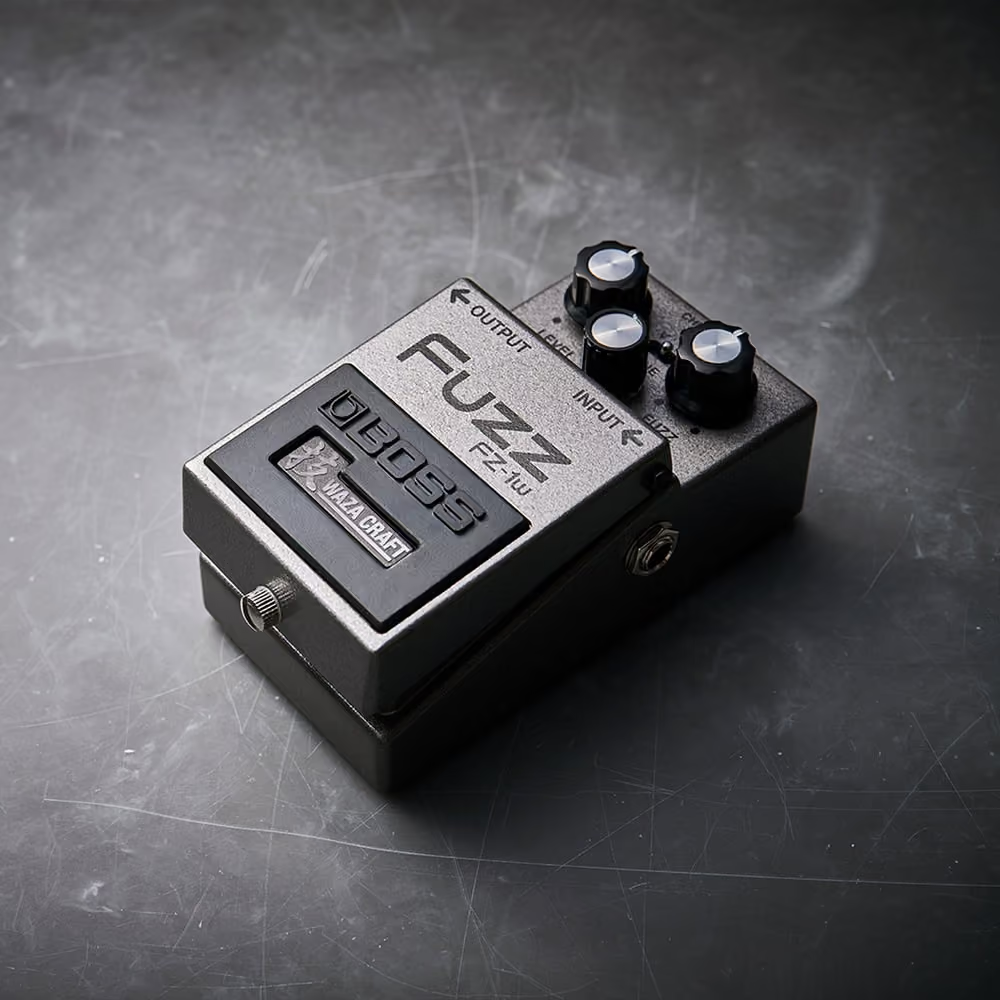
Week 06 Stage: Nonlinearity
Inside Overdrive, Distortion and Fuzz
Photo: germanium · CC BY 2.0
Why does clipping sound different from circuit to circuit?
- InputA signal driven into a real nonlinear element
- ProcessGain stage, then a clipping stage, in one of several arrangements
- OutputA distinct family of new harmonics per circuit
Where we left off
From a mathematical curve to a real circuit
Week 5 showed that clipping a sine wave adds harmonic content that wasn’t there before, using clipping as an abstract mathematical transformation. But two circuits that both “clip the signal” don’t necessarily clip it the same way — and the shape of the clip decides which new harmonics appear. By the end of this week you should be able to identify the stages of a simplified distortion pedal; explain how a gain stage and a clipping stage divide the work; distinguish symmetric from asymmetric clipping by their effect on harmonic content; compare clipping-to-ground with feedback-loop clipping conceptually; and explain why overdrive, distortion and fuzz are different kinds of nonlinearity rather than different amounts of one effect.
- Gain stage
- Clipping stage
- Harmonic content
- Perceived character
Inside a simplified pedal
Gain stage, then clipping stage
The gain stage raises the signal past the level the next stage can pass without limiting it — the more gain applied here, the harder the following stage clips. The clipping stage is where Week 5’s abstract “clipping function” becomes a real circuit, usually built from diodes: a diode conducts more readily in one direction than the other, arranged across a signal path that imposes a soft limit on the waveform. This is a conceptual model of what a diode does here, not a full account of semiconductor physics.
Pushed far enough, the waveform’s peaks start to flatten before they ever reach the clipping stage’s threshold — headroom is what “far enough” means.
Symmetric vs. asymmetric
Two axes of clipping shape
Circuit context
Where the clipping element sits
Two different circuit contexts for the same diode behaviour produce two different input-output curves — one reason two “distortion” circuits built from similar parts can still sound different. Fuzz circuits usually push further than a single diode pair — extra gain stages and stronger waveshaping than simple diode clipping — but there isn’t one fuzz topology to name: it’s a family of stronger, often less predictable transformations, not a fixed extra notch on a “how distorted” dial. Anything more specific — a named pedal, a transistor type, a historical circuit’s component values — would need a real source, and none is asserted here.
Try it
The nonlinearity simulator
- Physical mechanism
- Signal transformation
- Waveform / spectral consequence
- Audible consequence
The Pedal view below is what a musician touches: a gain knob, topology footswitches, a source switch, and a play switch. Flip to Engineering to see what those controls actually did to the signal — its transfer curve, its waveform before and after clipping, and the resulting spectrum. This is a fictional test instrument, not a replica of any real pedal.
Audio never plays automatically — press play to hear it, press again to stop.
LAB TONE — pure sine, for reading the transfer function cleanly
The waveform and spectrum above read the signal right at the clipping stage. The Guitar source you hear also passes through a fixed listening filter afterwards — a stand-in for "played through something", not a taught cabinet model.
Takeaways
What this week establishes
A distortion pedal separates “how hard to drive the signal” (the gain stage) from “how to limit it” (the clipping stage).
Symmetric clipping mostly reinforces existing odd harmonics; asymmetric clipping introduces a different harmonic balance.
The same nonlinear element produces a different transfer curve depending on where it sits in the circuit — directly across the signal, or inside a feedback path.
Fuzz is a family of stronger, more varied nonlinear transformations, not a fixed amount more of the same clipping.
Overdrive, distortion and fuzz are distinguished by the shape of the nonlinearity, not by a single intensity scale.
The chain
Where this sits, and what comes next
- 01INPUTWhat Is Guitar Tone?
- 02STRINGThe Vibrating String
- 03PICKUPFrom Vibration to Voltage
- 04CIRCUITThe Guitar Is a Circuit
- 05DRIVEGain, Headroom and Clipping
- 06DISTORTIONInside overdrive, distortion and fuzz
- 07FILTERFilters, EQ and Tone Stacks
- 08MODULATIONModulation: Phase, Pitch and Motion
- 09SPACEDelay, Reverb and Space
- 10AMPInside the Guitar Amplifier
- 11SPEAKERSpeaker, Cabinet and Air
- 12OUTPUTEngineering the Complete Tone
Week 5 introduced clipping as a mathematical transformation — an input-output curve that stops being a straight line once a signal exceeds a system’s headroom. This week implemented that transformation with real circuit elements: gain stages, diodes, and the different contexts a nonlinear element can sit in. Clipping’s real effect is to generate additional harmonic content that wasn’t in the original signal. Next week asks what happens to that new, wider spectrum once it reaches a filter — which selectively keeps, removes, or emphasises parts of it, rather than passing all of it through unchanged.
- Physical mechanism
- Signal transformation
- Waveform / spectral consequence
- Audible consequence